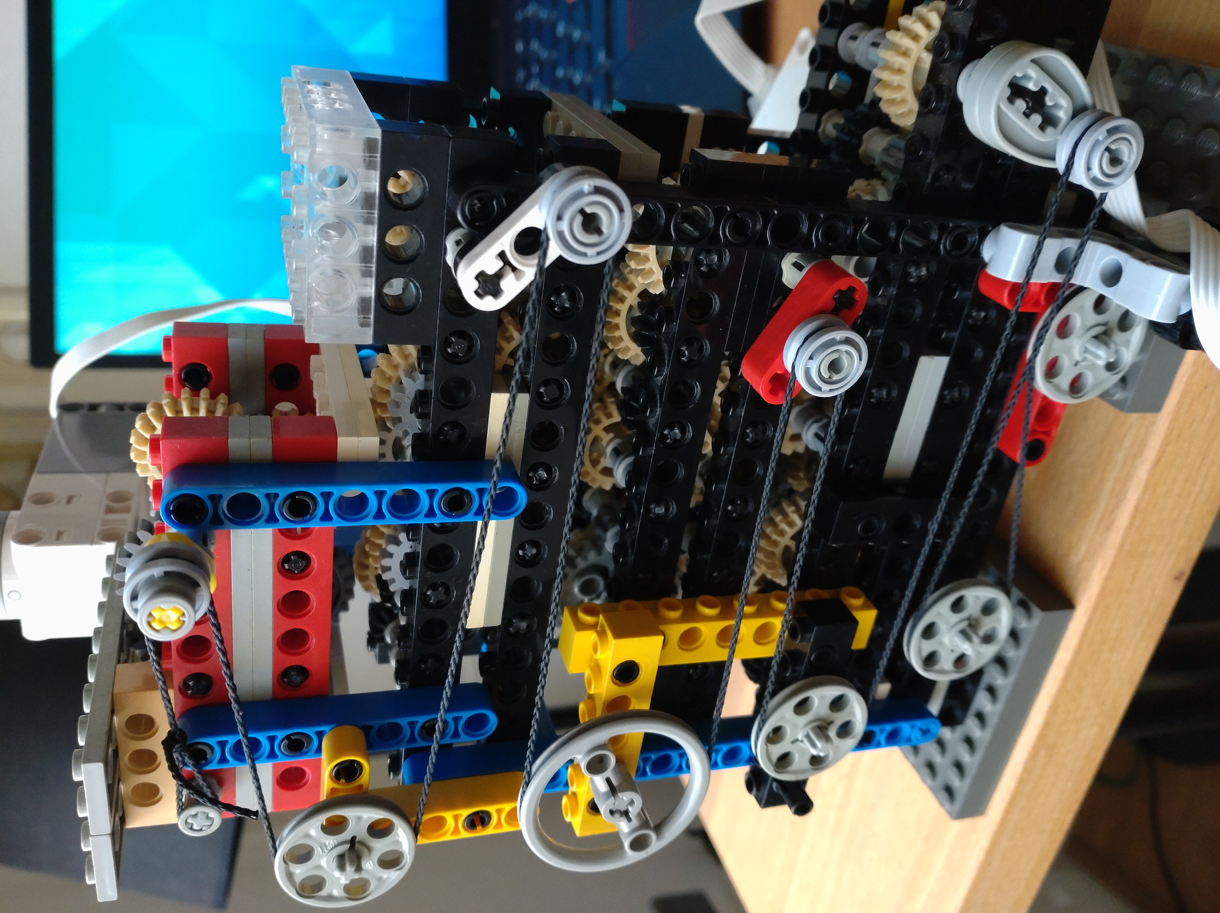
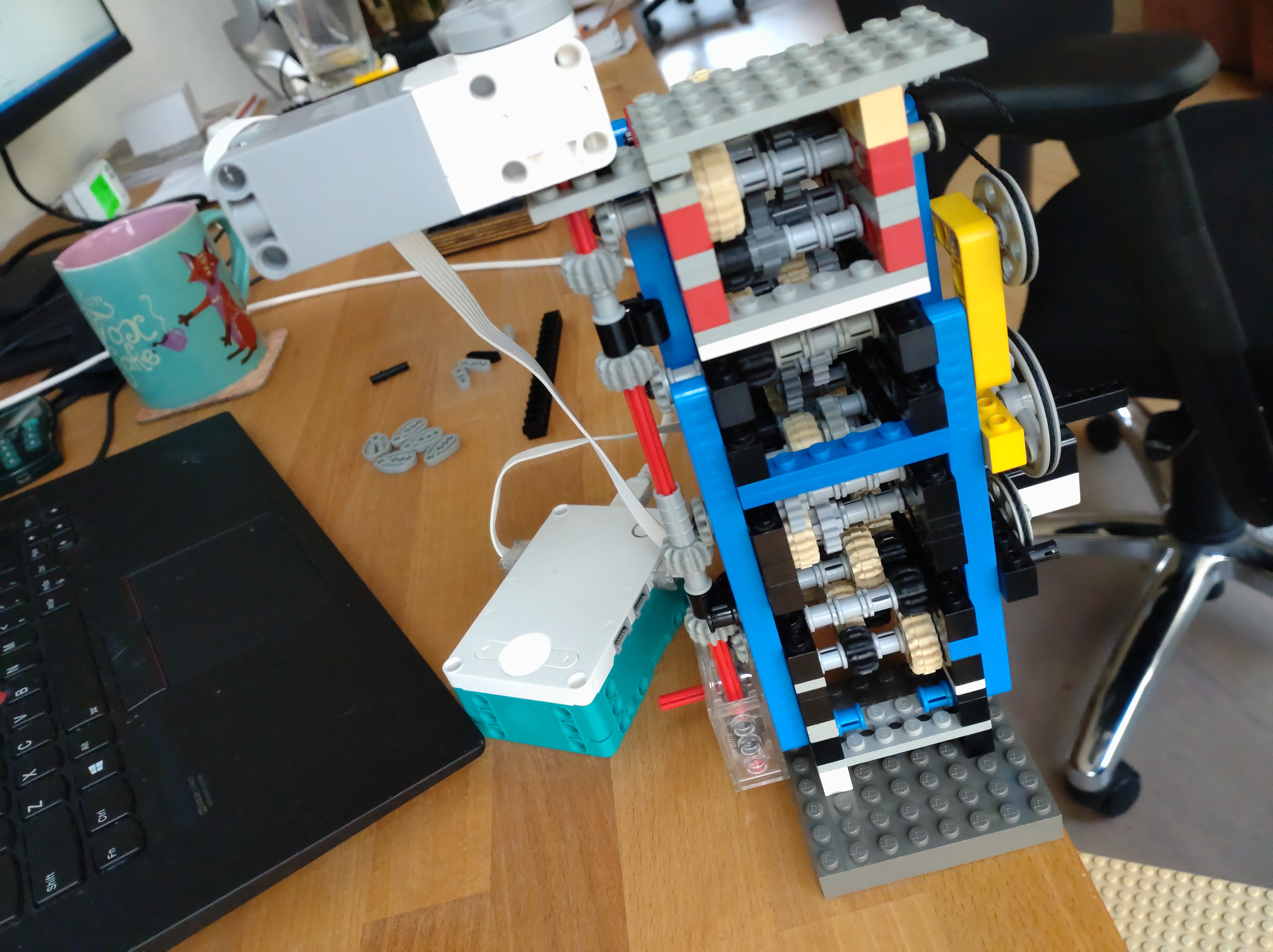
Inspired by a great video by Veritasium about analog computers and Andrew Carol’s Lego Antikythera mechanism I decided to try to build Sir William Thomson’s tide predicting machine out of Lego. Before I get into the details, here is a video of it running.
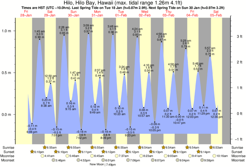
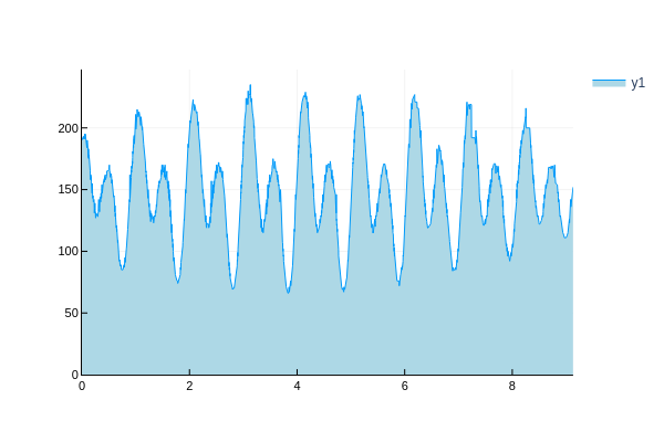
It uses 96 gears and a Lego Robot Inventor to drive the device and measure the hight of the output with an ultrasonic sensor. The motor angle and distance are then logged to the computer to plot the tide over time. This is super exciting! Compare real tide data form Hawaii to the data generated by my machine. Looks similar right!! Of course not all components are aligned perfectly, but there is definitely a striking similarity.
With all the pretty pictures out of the way, time to get into the making of.
As Veritasium explains in his video, predicting the tides was alway an important problem, but only after we had been blessed with the Fourier transform, did it become possible to decompose tidal data in frequency components, and then add these components back up to predict the tide. Except this was before digital computers existed, so Sir William Thomson invented an analog computer with gears, ropes, and pulleys to create the different frequency components and add them together.
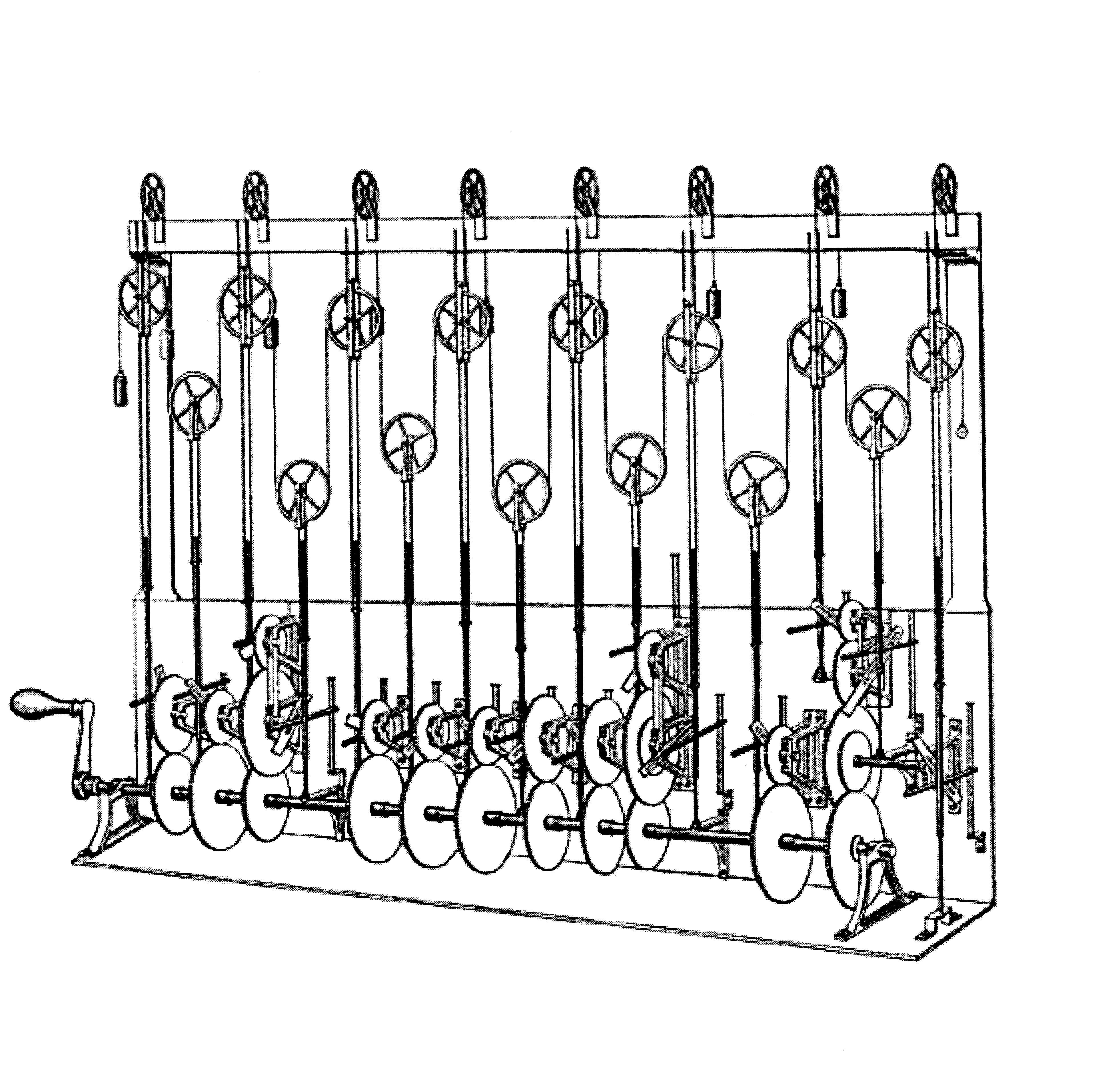
So the idea is simple. Create gear trains that run at the correct frequencies, and then attach pulleys to them. One small problem, Lego gears only come in a small set of fixed sizes, so you can’t just make a 468/424 gear ratio by meshing a 468 and a 468 tooth gear, you have to build it up from the fixed gear ratios that you have. This turns out to be a bit of a challenge. To solved it I wrote a Julia script to find the optimal gear ratios.
To save me half of the problem, of decomposing tidal data into frequency components, I found that the Wikipedia page Theory of Tides contains a handy table with the frequencies of the components, and their magnitude at various locations. I only took the 5 biggest ones.
First I defined all the frequencies and normalized them and scaled them down. This is important because all these gears will have a ton of friction and backlash, so by introducing reduction both of these problems can be reduced a lot.
using Optim
M2 = 12.4206012
S2 = 12
N2 = 12.65834751
K1 = 23.93447213
O1 = 25.81933871

periods = 1 ./[M2, S2, N2, K1, O1] .* 12 ./ 24
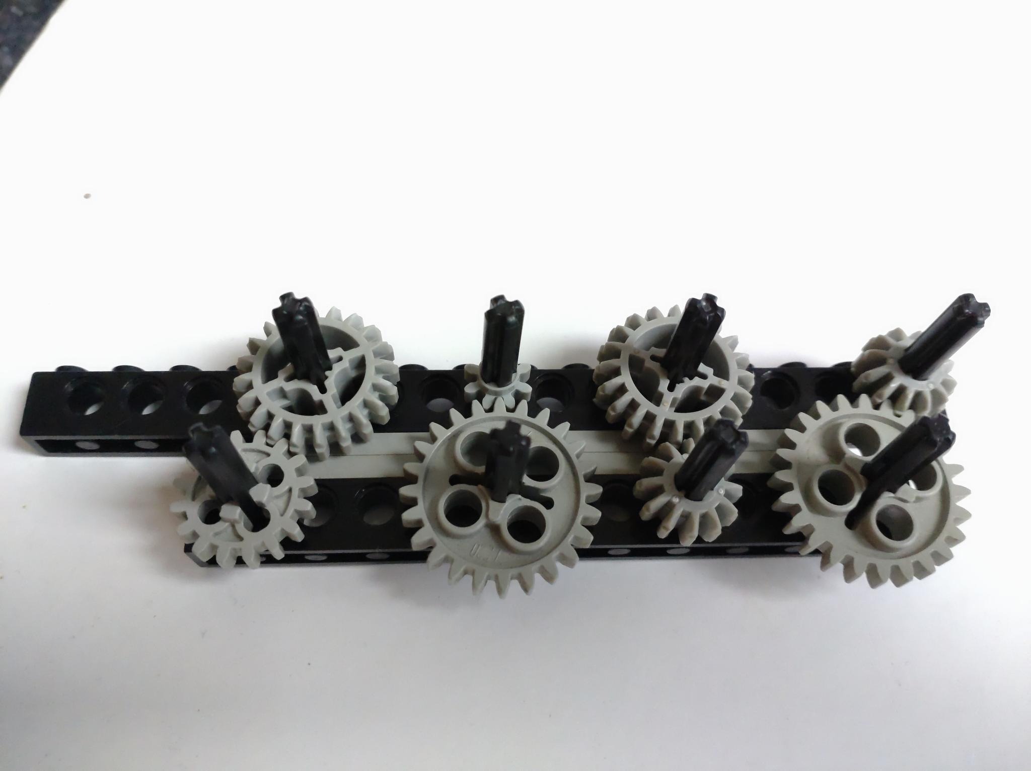
Then I computed all the possible gear ratios you can make out of Lego gears. But I later found that not all combinations are easy to build, in fact some are downright impossible (12:16 for example). So I narrowed down the list to just 4 combinations: 8:24, 12:20, 12:28, 16:20. I found that these 4 ratios required almost the same amount of gears as using all combinations, but gives a result that is much easier to build. These can all be assembled on a normal grid of technic beams.
gears = [8, 12, 16, 20, 24, #=36, 40=#]
gearratios = Dict{Rational{Int64}, Vector{Tuple{Int64, Int64}}}()
for g1 = gears
    for g2 = gears
        if g1 < g2
            push!(get!(gearratios, g1//g2, []), (g1,g2))
        end
    end
end
delete!(gearratios, 12//16) # impossible
delete!(gearratios, 36//40) # huge
delete!(gearratios, 20//36) # wide gap, large
delete!(gearratios, 16//40) # wide gap, large
delete!(gearratios, 20//24) # wide gap
delete!(gearratios, 8//40)  # large
delete!(gearratios, 16//24) # large

grs = []
for gr = values(gearratios)
    if length(gr) == 1
        push!(grs, gr[1])
    else
        push!(grs, first(filter(x-> 8 ∉ x, gr)))
    end
end
Then I ran a simulated annealing algorithm to find the optimal gear ratios. I formulated the problem as a big product of all the gears, where I can optimize the exponents to vary the number of gears. Negative exponents just flip the gears around. I added a small factor for the required number of gears so it’d hopefully find an optimum that also doesn’t require 500 gears like my first attempts.
\[\prod_{i=1}^4 R_i^{n_i} + A\sum_{i=1}^4 |n_i|\]A final little trick I used to reduce the number of gear is that the neighbor function tries a random permutation that doesn’t exceed the hard limit on the total number of gears I set. Playing around with this a bit I got much better convergence to much more reasonable results. Note that the final result uses less than this limit! It just stops the optimizer from generating too much BS proposals.
x0 = zeros(length(gearratios))
lim = 20

function neighbor(x::AbstractArray, x_proposal::AbstractArray)
    while true
        for (idx, xval) = enumerate(x)
            val = rand((1, 0, -1))
            x_proposal[idx] = xval+val
        end
        sum(abs.(x_proposal)) < lim && break
    end
end

temperature(t) = 1/log(t/1000)

ngs = ones((length(periods),length(gearratios)))*lim
for (idx, ratio) = enumerate(periods)
    cost(x) = abs(prod(keys(gearratios).^x)/ratio-1)+sum(abs.(x))/1e4
    res = optimize(cost, x0, SimulatedAnnealing(;neighbor, temperature), Optim.Options(iterations = 10000000))
    mg = Optim.minimizer(res)
    mm = Optim.minimum(res)
    ng = sum(abs.(Optim.minimizer(res)))
    ngs[idx,:] = mg
    println()
    println(ratio)
    println(mm)
    println(mg)
    println(ng)
end
And then all that is left to do is compute the bill of materials and verify the error margin looks fine.
num = sum(abs.(ngs); dims=1)
thebom = Dict(zip(gears, zeros(Int64, length(gears))))
for (num, (g1, g2)) = zip(num, grs)
    thebom[g1] += num
    thebom[g2] += num
end
thebom

display([permutedims(grs); ngs])
display(thebom)
display(sum(values(thebom)))
res = map(x->float(prod(keys(gearratios).^x)), eachrow(ngs))
display(res./periods)
display(res.-periods)
Pretty good!
6×4 Matrix{Any}:
   (12, 20)   (12, 24)   (16, 20)    (8, 24)
  1.0        1.0        9.0         0.0
  0.0        3.0        0.0         1.0
 -1.0        0.0        2.0         3.0
 11.0        0.0        2.0        -2.0
  9.0        0.0        2.0        -1.0
Dict{Int64, Int64} with 5 entries:
  16 => 15
  20 => 37
  12 => 26
  24 => 11
  8  => 7
96
5-element Vector{Float64}:
 1.0002389240748448
 1.0
 1.0001657291851853
 1.0003226141581112
 0.9991658743311826
5-element Vector{Float64}:
  9.618055961925498e-6
  0.0
  6.546240931305791e-6
  6.739529419302198e-6
 -1.6153118369648806e-5
Now one last simple thing I need to calculate is the length of the levers to match the amplitude of the frequency components. Looking at the table on Wikipedia I picked Hawaii because the differences in magnitude are relatively small. That means I will not have to make a lever of 20 studs and one of 0.2 studs.
Normalizing the amplitudes to 2 studs for the biggest component, resulted in a smallest component of a bit shy of 0.5 studs. I rounded these distances to 0.5 studs, which resulted in levers of 0.5, 1, 1.5, and 2 studs. Very reasonable! I experimented with variable length levers, but they were too flimsy.
5-element Vector{Float64}:
 2.0
 0.7999999999999999
 0.3826086956521739
 1.452173913043478
 0.7999999999999999
Next, I took my bill of materials to Bricklink, robbed some poor seller of literally all of their gears (I had to supplement some types from my existing collection because they didn’t have enough!), and two weeks later I could start building.

Packing all these gears as tightly as possible was a real challenge. The diagonal ones can just zig-zag around,but the orthogonal ones require a sort of snake pattern that’s extremely tight. Each axle has 4 positions and is surrounded by 5 other axles, meaning the smaller gears have to double up. But after two days of trying, I was successful. The first one took forever, an then the rest was done in a matter of hours.
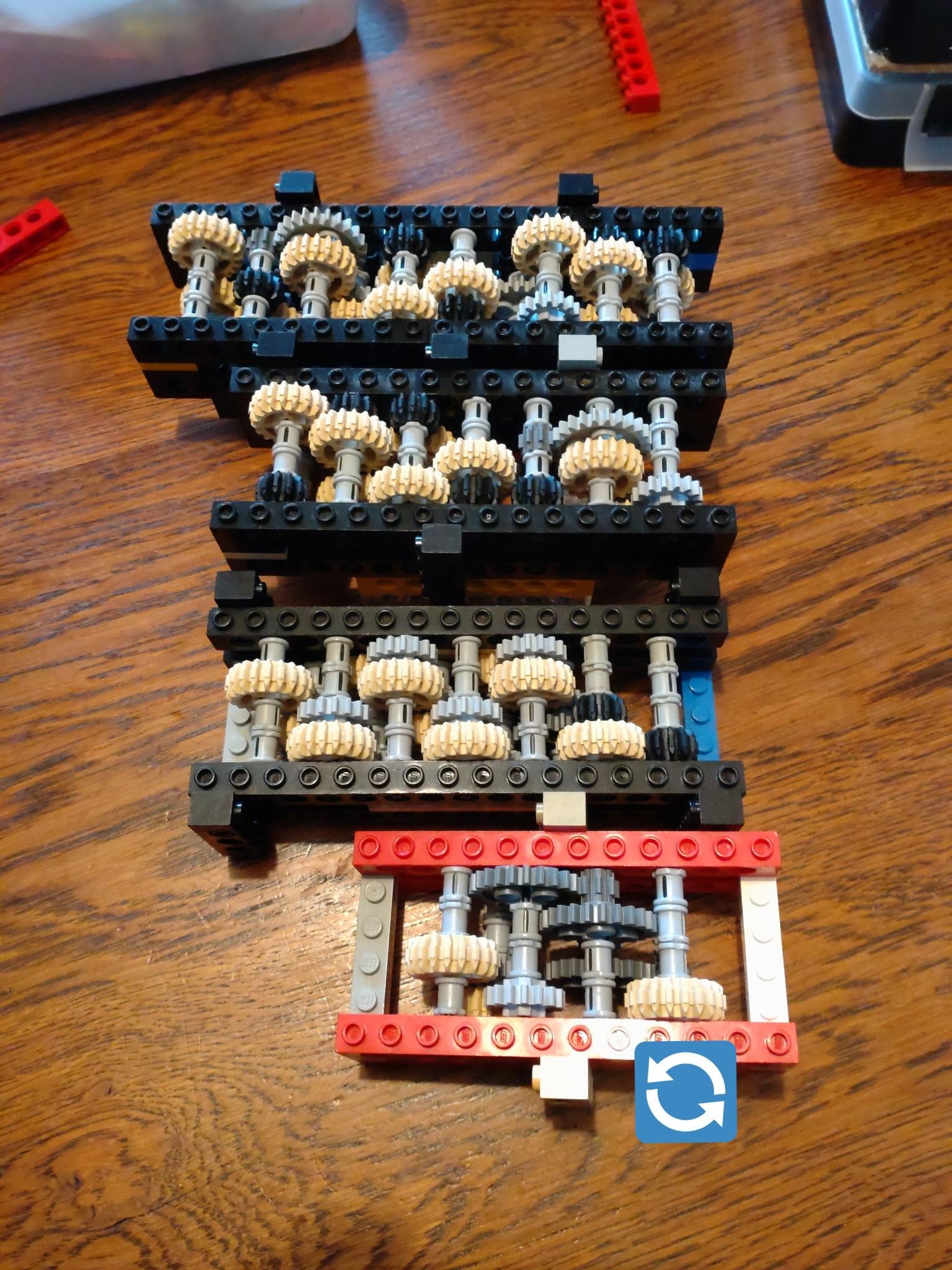
After that I stacked them on top of each other, and hooked them up with a long driveshaft, attached levers and pulleys, and the rest is history.
If you’re looking at the video and wondering which gear train corresponds with which frequency components, but don’t want to go figure it out from pictures of gears, here is an annotated picture. Green are the semi-diurnal ones, red the diurnal ones, which are twice as slow.