Ever since I made my wooden mouse using this ADNS-9800 breakout, I’ve been getting emails and comments asking for help connecting the ADNS-9800 to a Teensy and programming it.
So this is my attempt at writing down all stuff you need to know. I promise it’s not hard if you know anything about Arduino and programming. If you don’t, you might want to reconsider your mouse-building plans.
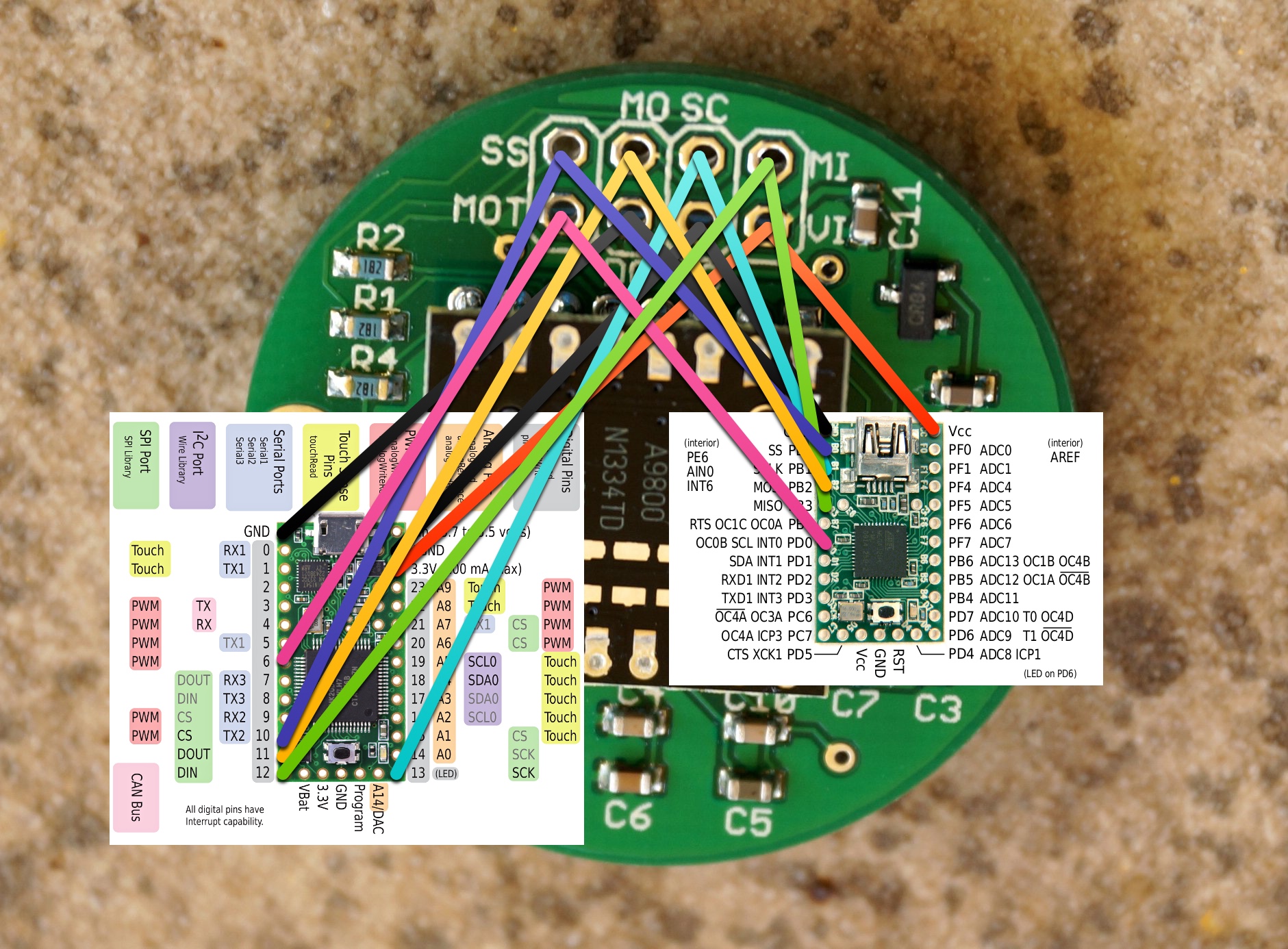
It seems to be a bit confusing to some people how to connect the wires. On the breakout is a 2x4 header with labels, and the author has helpfully provided a list of what they do. (with a few minor additions of mine)
- MI = MISO (Master In, Slave Out) (DIN on Teensy 3)
- MO = MOSI (Master Out, Slave In) (DOUT on Teensy 3)
- SS/SC = Slave Select / Chip Select
- SC/SCK/SLCK = SPI Clock
- MOT = Motion indicator (active-low interrupt line)
- AG = Analog Ground (connect to common ground near power supply)
- DG = Digital Ground (connect to common ground near power supply)
- VI = Voltage in, up to +6V (See note about voltage)
Next you find the pinout for your Teensy and match up the labels.
It should be noted that slave select and the motion pin can be connected to any GPIO at all. Although a pin with an interrupt is preferred for the motion pin.
Another important fact is that the Teensy 3 runs at 3.3v while the Teensy 2 runs at 5v. From the author:
If you are using Arduino or another similar microcontroller that has a native 5V core voltage, you’ll need to activate 5V mode by cutting the tiny traces between the three sets of exposed pads on the 3.3V side of the board and adding three solder bridges to the exposed pads on the 5V side of the board.
Next up, you install Teensyduino, read the example code or the code for my mouse and adapt it for your needs.
You’ll see there is one file with a binary blob that is the firmware for the sensor. This is loaded at startup by the other file containing the main program.
At the top you’ll find a list of all the registers, the meaning of which can be found in the datasheet.
Then the SPI is initialised and perform_startup is called to start the sensor. Finally a FALLING interrupt is attached to the MOT pin. This triggers when the sensor has moved. When this happens you pull low the CS and read the motion registers with adns_burst_motion.
At the bottom of my code are a bunch of functions named adns_*. They are mostly copied from the example code and can be used to to read/write registers on the sensor.
Good luck!