In university we currently learn about MOSFETs and BJTs, but valves(vacuum tubes) are completely absent from the material. Of course valves are essentially obsolete, and I’ve seen before that they try to avoid letting students work with hundreds of volts, but valves interest me.
I mean, how could you not be interested in glowing tubes with vacuum. The other part is that some audiophiles claim they produce superior sound. But sometimes audiophiles are full of bullshit, so I’d better verify all those claims for myself.
The plan
I might eventually actually use hundreds of volts on my valves, but for now the plan is to operate them at a low voltage and use modern transistors to create an output buffer.
I draw inspiration from this 12v headphone amp and this document about triodes at low voltages.
The point is that you can operate valves at low voltages, but they just provide very low current. So you need a separate output stage to drive anything.
The referenced designs use an A-class source-follower for the output. Some claim that even though they have terrible efficiency, can have less distortion than AB-class output stages. This will be tested of course.
Equations please
For MOSFETs and BJTs I learned how to use mathematical models to design amplifier stages. For valves, I could not find any such models. I asked the professor, and he referred me to the MOSFET equations in ohmic mode:
\[I_A= K \left( (V_{GK}-V_{th})V_{AK}-\frac{V_{AK}^2}{2} \right)\]But with K and \(V_{th}\) not known, this is not very useful. I asked around a bit, and it seems that people just take the graphs from the datasheet and use them for biasing. But as said in the linked PDF, voltages in the datasheet range from 50 to 200 volt usually, so we’ll have to make our own graphs.
To do so, I used the NI MyDAQ arbitrary waveform generator, oscilloscope, and an XY-plot to plot the relation between grid voltage and anode current at several anode voltages.
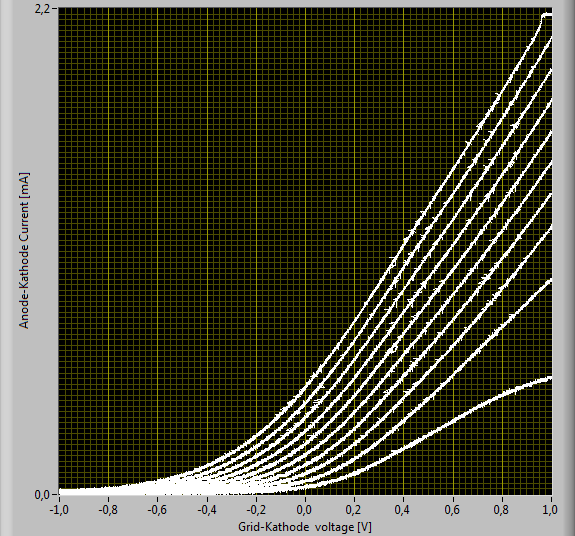
In this graph I plotted the anode current for anode voltages from 1v to 10v and grid voltages from -1v to 1v. Current never exceeds 2.2mA for 10v.
But valves are always biased with negative voltages, even though a positive voltage clearly gives more current. To see why, we need to look at grid current.
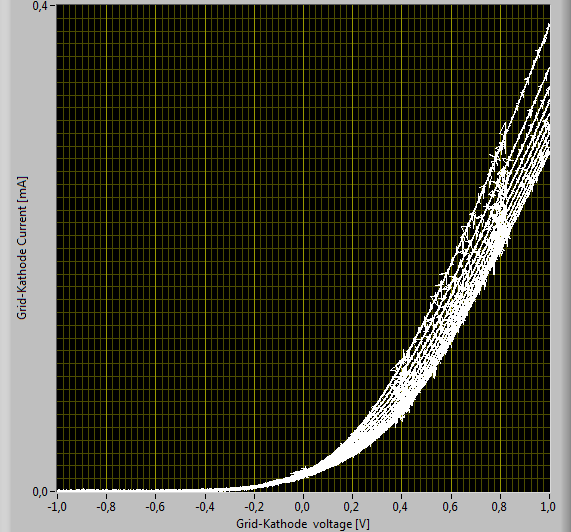
As can be seen, for positive grid voltages, the control grid starts to leak current to the cathode, which is undesirable. But as described in the linked PDF, this current itself can be used to bias the valve.
Class war
I read a lot about the advantages and disadvantages of A-class, B-class and AB-class amplifiers, but most of it is not very scientific.
One thing is for sure, A-class uses a lot more power and is at best 25% efficient. When the output is at rest, a constant current is just dissipated as heat. When the output is low, that is the amount of current that can be drawn. But when the output is high, it needs to supply double that current, of which half is just burned and the other half flows into the output.
A more interesting and vague topic is distortion. It is claimed that distortion in A-class amps is mainly even harmonics and B-class distortion is mainly odd harmonics. Why this is the case and why the one would be superior is not frequently explained.
Why even harmonics are more pleasing is understandable. First, it is important to understand that harmonics drop off in amplitude very quickly, so you mostly hear the first few. If you look at the first harmonics, you see that the even ones are octaves, while the odd ones are fifths and thirds.
Octaves are just the same note, but twice as high. It seems reasonable to assume this sounds more pure and full than odd harmonics, which are other notes altogether.
But why, how, and by how much?
Equations please
The voltage-current relationship of a BJT is
\[I_D=C_0\left(e^{\frac{q}{Kt}V_{be}}-1\right)\]If you squint a bit, you could say that the output current is an e-power of the input voltage. Taking a cosine for the input, we can formulate equations for A-class and B-class amps.
\[\begin{aligned} f_a(x)&=e^{cos(x)}\\ f_b(x)&=\frac{1}{2}(e^{cos(x)}-e^{-cos(x)}) \end{aligned}\]To take a look at the harmonics we can calculate the Fourier series for these functions. Except the indefinite integral of this equation does not exist. So instead I kindly asked my CPU to perform the following integral numerically for me. (the sine coefficients are trivially 0 since \(f(x)=f(-x)\))
\[a_n=\frac{1}{\pi}\int^{\pi}_{-\pi} f(x)cos(nx) dx\]| Harmonics | 1 | 2 | 3 | 4 | 5 | 6 |
|---|---|---|---|---|---|---|
| A-class | 1.1303 | 0.2714 | 0.0443 | 0.0054 | 0.0005 | 0 |
| B-class | 1.1303 | 0 | 0.0443 | 0 | 0.0005 | 0 |
From this you can clearly see that odd B-class harmonics are identical to the A-class harmonics. The interesting part is that the even harmonics are gone. They simply cancel out.
Of coures, you can build either class with very low distortion, but for the same biasing/distortion level, B-class will have less overall distortion, but concentrated entirely in odd harmonics. Meanwhile, A-class has a more balanced harmonic distribution, which might sound more pleasing if the overall distortion is low enough.
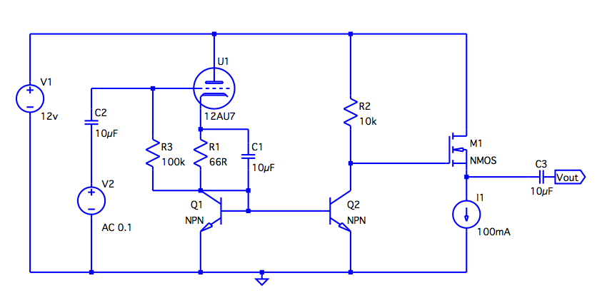
Initial design
Initially, I’m mostly going to use the design of the linked headphone amp and iterate based on that. There is one major change though.
While transistors operated in the saturated region don’t depend on drain/collector voltage, valve anode current depends linearly on anode voltage.
As described, the linked headphone amplifier uses a variable resistor that is tuned such that at rest the output voltage sits at the center of the available range, meaning there is only 6v across the valve instead of 12v.
Instead I used a current mirror so that there is a constant 11.4v across the valve. The current is then mirrored to the other BJT, where it drops over the resistor connected to the buffer to create the output signal.
Normal cathode biasing is used for now, but grid-leak biasing will also be tested later.
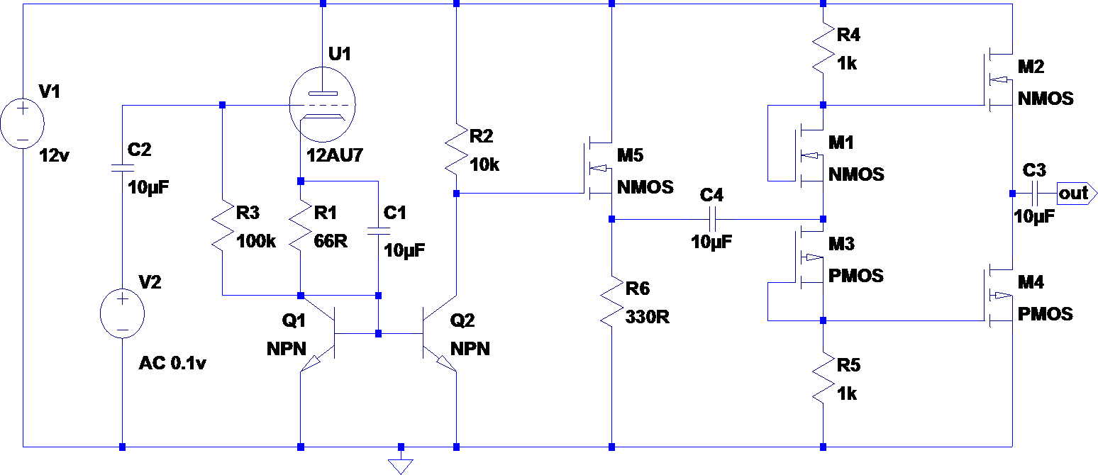
AB-class design
The gain stage for this design is unchanged, but an AB-class output stage is added.
It turns out the input impedance of the output stage is \(1k//1k=500\Omega\), which created a nice current divider with the current mirror. So I had to add another follower stage as a buffer.
Execution
I built the first design and after making sure it looks okay on the oscilloscope I connected it to an electric guitar and an old pair of headphones, and it worked!
Initially I used a cheap wall wart to power the amplifier, but this gave a lot of noise and hum. Now I switched to an old PC power supply, which is not perfect either, but at least the 50Hz hum is gone.
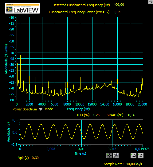
For the A-class circuit the THD is about 1% to 2% depending on god knows what.
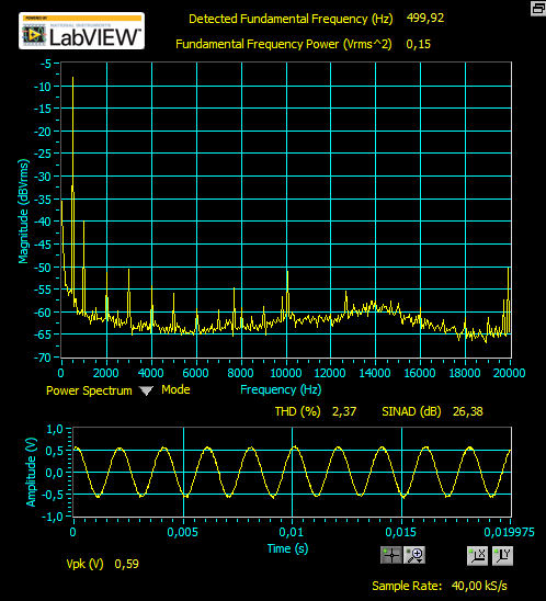
The AB-class circuit does not have the nice space-heater output stage, and performs slightly worse than the A-class circuit with a THD of around 2% to 3%.
Interestingly, the harmonics are about the same. Both have strong even harmonics and nearly no odd harmonics. Whether these harmonics are caused by the gain or the output stage remains to be seen. So much for theory I guess.
To be continued…