My brother scavenged and repaired an old bass guitar, and asked if I could make him an equally bad amplifier to go with it to create the ultimate bad sound.
I was happy to oblige, so I threw everything I know about good amplifiers out of the window and googled around for some inspiration. Thus resulted in a lot of badly designed amplifiers, that subject your speaker to DC currents or don’t deliver any power at all.
So I started making some myself. First thought was to make a class A amplifier with a single power MOSFET and power resistor. I got two 1 Ω resistors in series, rated for 5 W. This gives a maximum voltage of 2.2 per resistor.
\[P=IU=\frac{U^2}{R}\rightarrow U=\sqrt{R P}=\sqrt{5}=2.2\]The MOSFET is rated for 30 A, so that’s probably fine. Then I used a potentiometer to bias the gate and a capacitor to drive it. Something like this.
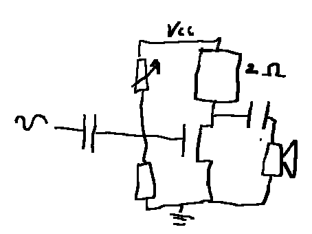
Problem is, while it’s a very nice and simple space heater, it does’t sound bad enough. It’s inefficient and non-linear, but the sound is kind of fine.
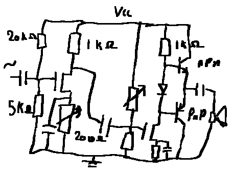
So the next step was to make an amplifier that sounds worse. What better than a pure class B output stage with its sweet unmitigated crossover distortion?
I pulled a complementary pair of BJTs from a drawer, and drove it with some random small-signal MOSFET and a 1K resistor. A diode was added to reduce the cross-over a bit. The output cap is just a large one. At the bottom of the MOSFET I added a 100 Ω degeneration resistor that I bypassed in AC with a capacitor for more gain. I again added a potentiometer to bias the MOSFET.
My brother liked the bad sound, but it wasn’t loud enough, so I added another MOSFET gain stage. Same story, 1K resistor, small bypassed degeneration resistor, and a potentiometer to bias the MOSFET. Except now I put the potentiometer as the degeneration resistor, for no good reason.
Neither of these amplifiers involved much design, calculation, or simulation. They were directly constructed on overboard with potentiometers where I would have needed math to find the correct value, and I just made these drawings for this post.
Normally what you’d do is calculate the gate voltage created by the voltage divider.
\[V_G=V_{CC}\frac{R_1}{R_1+R_2}\]The voltage across the degeneration resistor is then roughly
\[V_S=V_G-V_{TH}\]For a BJT the threshold voltage is roughly 0.6 V while a small-signal MOSFET is more like 2 V. Ohms law then gives you the current through the degeneration resistor, which is the same current as through the 1k resistor at the top, so you know how much voltage drops across that one.