When making a modular synth, everything has to be voltage controlled. So how do you make a voltage controlled amplifier, a voltage controlled oscillator, or a voltage controlled filter? One way is with an operational transconductance amplifier.
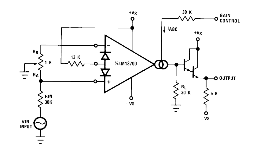
The LM13700 is like a swiss army knife of voltage control. Its datasheet is completely packed with refference circuits for voltage controlled everything. To get familiar with its operation, I built a few of the circuits on breadboard.

Basically an OTA is like an opamp with current output, but it’s frequently used without feedback. To make the differential pair more linear, biasing diodes are used at the input. But the linear range is still limited to a few dozen millivolt. What makes it voltage controlled is that the current gain is controlled by IABC, which is the tail current of the differential pair.
For my test circuit I hooked the current gain up to a button with an RC network connected to it, so it does a nice attack and decay when pressed and released.

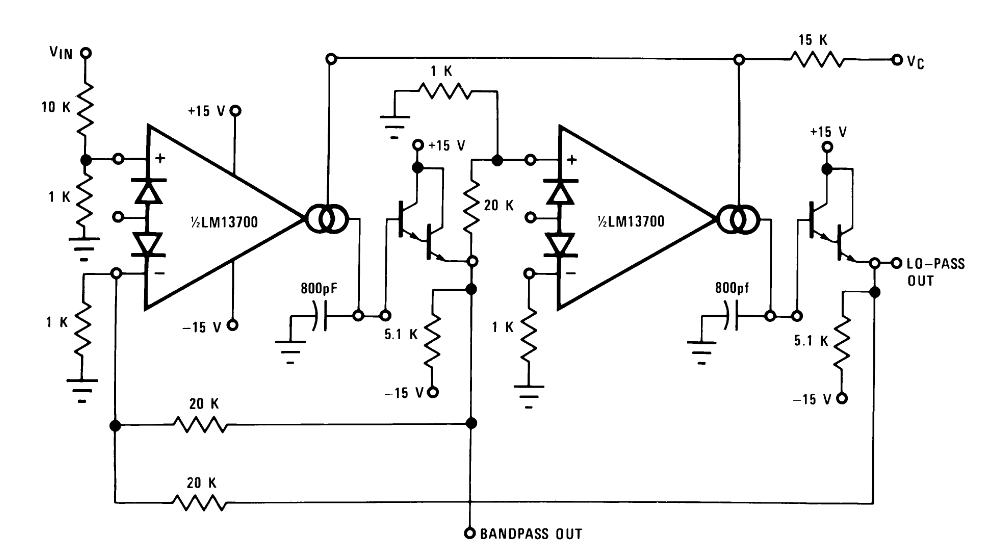
Then I fed the output of my VCA into this beautiful state variable filter. What is cool about state variable filters is that they can have low-pass, high-pass and band-pass outputs from the same signal. Each OTA basically forms a Gm-C filter. Put simply, a resistor’s current depends on the voltage you put on it, and so does the current of the OTA depend on its input voltage.
For the above video, I output white noise and a low-frequency sine from the MyDAQ. The white noise goes through the VCA controlled by my RC button envelope, and through the band-pass output of the state variable filter, controlled by the slow sine wave.
