What if you took a boost converter and converted it to the rotational mechanical domain? Switching CVT!
At the University of Twente, they teach Bond Graphs, a modelling system for multi-domain systems that is just perfect for this job. Unlike domaing-specific systems or block diagrams, Bond Graphs model a system as abstract connections of power. Power is what you get when you multiply an effort with a flow. The two examples we’re interested is voltage × current and force × velocity, or to be exact, angular momentum × angular velocity.
Here is a schematic of a boost converter (source). It goes from a high voltage (effort, force) to a low voltage, but from a high current (flow, velocity) to a low current. It works by charging the inductor by shorting it to ground, and then discharging it via the diode into the capacitor.

The classic example of model equivalence is that an electrical inductor-capacitor-resistor system behaves equivalent to a mechanical mass-spring-damper system. In the rotational domain, the equivalent of a switch is a clutch, and the equivalent of a diode is a ratchet. So we have all we need to convert the system! Step one is making the bond graph from the electrical system.

Quick Bond Graph primer if you’re too lazy to read the Wikipedia page. Se is a source of effort. R, I, and C are generalized resistance, inertance, and compliance. mR is a modulated resistance I used for the switch/clutch. D is a diode/ratchet that I just made up. 0 junctions are sum of flows, equal effort. 1 junctions are sum of effort, equal flow. An ideal electrical net has equal voltage (effort), and a sum of currents, but a mechanical joint has an equal velocity (flow), but a sum of forces. With that in mind, we can convert the bond graph to the mechanical system.

I’m not sure if those are even remotely sane mechanical symbols, so I added labels just in case. The motor spins up a flywheel, and then when the clutch engages it winds up the spring. Then when the clutch is disengaged, the ratched keeps the spring wound up, driving the output while the motor can once more spin up the flywheel.
It works exactly analogous to the boost converter, and also suffers from the same problems. Most ciritically, switching/clutching losses. I imagine applying PWM to your clutch will at best wear it down quickly, and maybe just make it go up in smoke. Like with a MOSFET, the transition period where there is a nonzero effort and flow on the clutch, there is power loss and heat.
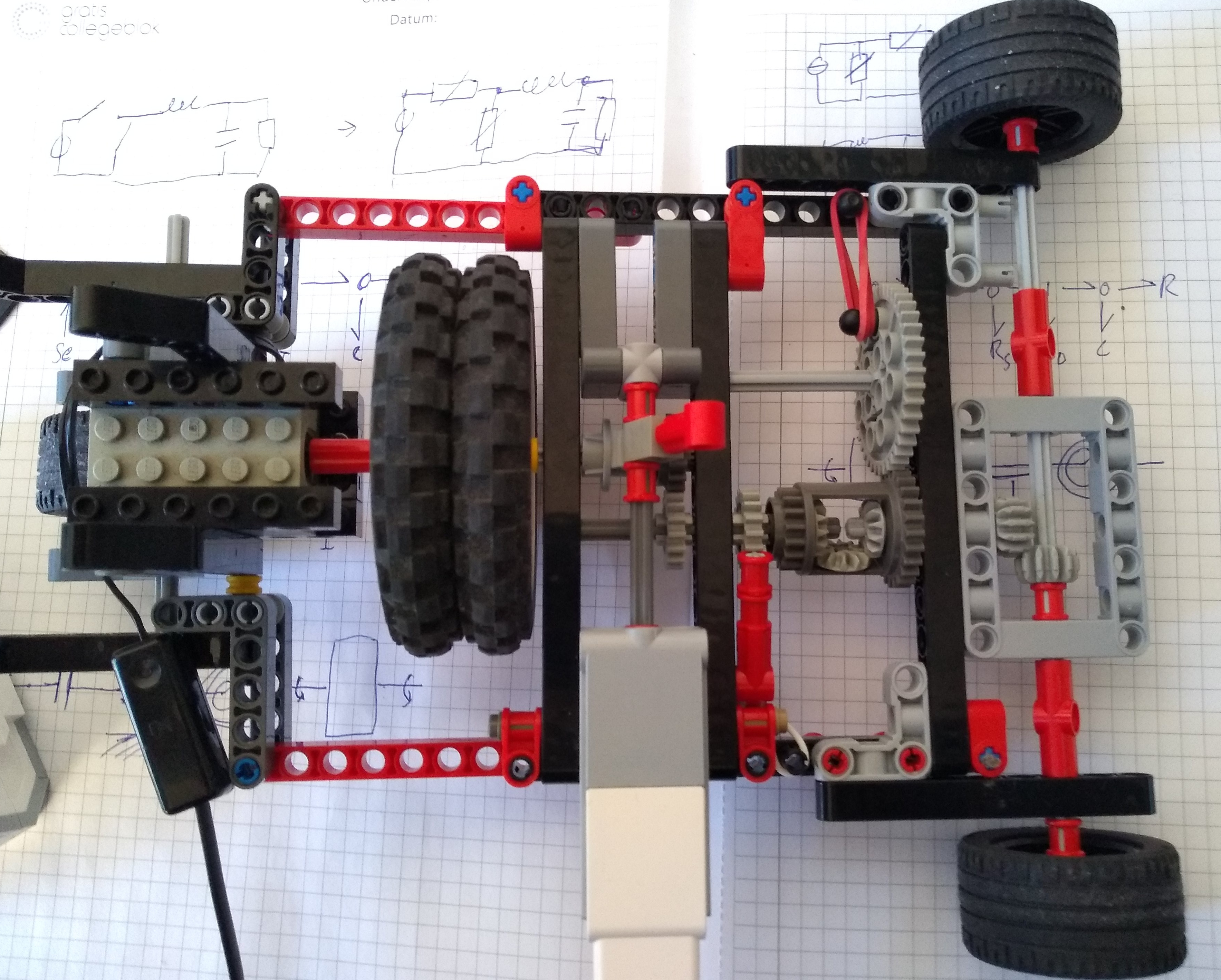
Anyway, I decided to build it in LEGO to see if it’d work. I used a high-speed ungeared motor that can drive absolutely no load at all, and connected it with a 1:1 gear ratio to the wheels with only a flywheel, clutch, ratchet, and spring inbetween. This proves that there is actually power conversion going on!
If you get rich making cars with this CVT system, please spare me a few coins. If you burn out your clutch… I told you so ;)
