Wishful Coding

Didn't you ever wish your
computer understood you?

Incremental E-paper update

This is what I’ve been up to since last post. I almost completely rewrote the Arduino code to support different waveforms and both full updates and incremental ones.

I admit the old update looked smoother, but it faded away over time, defeating on of the main features of E-paper, that it is bi-stable.

I do think the incremental updates look cool, kind of like an evolving Pokémon.

Get the source code

I am using a modified version of shiftOut that can send any number of bits. This is needed to send 1 bit for the background and common, and 16 bits for a character.

The EIO pin is no longer used, but just tied low. This causes the first chip to be selected when it wakes up. The enable pins are chained so that when the first chip is full, it pulls the second chip low.

In short, this is how I update the screen:

Step one is to convert all 8 bit characters to 16 bit segment data using a big table.

Next, I create a struct with the changes. This struct contains 6 arrays. One with the added segments, one with the removed segments, one with all changed segments and 3 negatives.

In case this is a complete update, this struct is very easy to make. In this case the negative of the aded segments equals the deleted segments.

In the case of a partial update, this struct is generated using a lot of binary logic, based on an array of the current segments.

Now that we have a struct of all the changes, we actually need to write this to the shift register and toggle the latch to send it to the display. The writing itself is fairly trivial, but the waveform is not.

I will cover the simple waveform in this post, and leave the 757 for you to figure out. The principle is the same.

First we wakeup the display. After every update, we shut it down again.

Now, you need to look at the datasheet to see the waveform for segments to white and segments to black. Unchanged segments need to be the same as the common bit, so no current flows through them.

Note that for white-on-black the added/deleted bits are the other way around, but the unchanged segments aren’t.

Finally, for every section of the waveform I take the corresponding array out of my changes, send it, and wait for a bit.
Improved library for Sparkfun E-paper display

I got my E-paper display from Sparkfun, but I was disappointed by the quality of the library.

My version has more and nicer looking(IMO) characters, uses black text on white background, uses sleep mode, and most importantly, no ghosting.

What remains to be done is implementing temperature awareness. The colder the display, the longer it takes to update. The Atmega chip has a sensor built in.

Original library
My updates

Thanks to the people at Hack42 for helping me out with my bootloader and understanding the E-paper datasheet.

One little byte of information that I found particularly interesting is that the E-paper controller is basically a shift register with an extra latch. Maybe the code can be simplified using shiftOut?

From the library

// Second ePrint removes the un-used segments - I know, this is weird…

I thought the same, until I understood the COM(mon) bit. This indicates that all specified segments should be pulled either high or low. But not both at the same time.

This means that the first pass, you put +35v on all the segments you want to use, and the second pass -35v on the ones you don’t want to use. Order doesn’t matter, but gives a different intermediate state.

Sparkfun 1.8v USB to serial

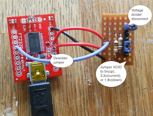
Sparkfun usb serial board with custom stripboard

I am trying to hack my Kindle 4 so that I can plug in a keyboard and use it as a Raspberry Pi with battery and E-paper screen.

To support a keyboard, the Kindle needs to use its USB port in host mode. This is called USB On The Go, and someone modified the Kindle kernel to support this.

So far, it does not work on my Kindle, but since the Kindle does not display any kernel messages while booting, I had no idea what went wrong.

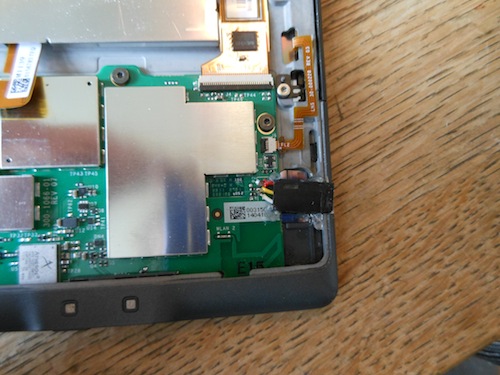
Thus, I had to open up the Kindle to attach a serial console. My brother is writing a guide about this at http://jurriaandevos.nl

kindle without back cover and with serial header

The next hurdle was that the Sparkfun USB-serial breakout comes with a solder jumper for 5v and 3.3v, but the Kindle uses 1.8v.

Therefore, I devised this small stripboard that lets you select any of these three voltages with 2 jumpers.

With the top jumper removed, you can switch the lower jumper to either jumper Vcc or the 3.3v reference to the VCIO pin.

With the top jumper connected and the bottom one in the lowest position, you engage a voltage divider between 3.3v and gnd, resulting in half that voltage(1.65v) on VCIO.

Before this works, you should desolder the built-in jumper, and remove the LEDs.

The LEDs are powered from Vcc, so they leak current into the circuit. I measured 2.7v on VCIO with the LEDs still on.

The voltage divider was made using two 10k resistors, but anything between 1k and 10k should be fine, I’ve read.

I’m looking forward to blog about my Kindle 4 keyboard soon.