My friends studying Industrial Design are currently doing a “smart product” project where they have to make an active 2-player game out of LEGO using the NXT and a launcher of some sort.
If I had to make such a game, I’d probably make a Twister robot that carefully calculates impossible positions and shoots at you while you’re struggling. Sounds fun, right?
But I don’t have to make such a game, so I can just have some fun making a launcher.
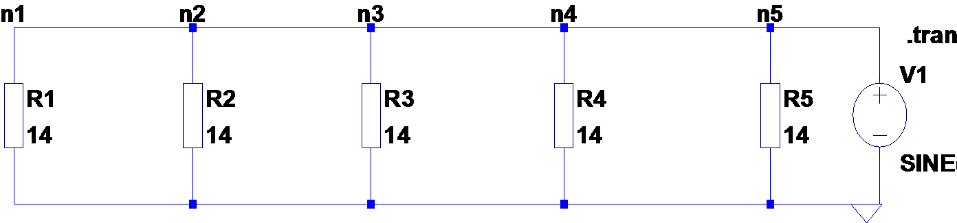
In a hall, two rows of 5 10W 12V lamps are connected in parallel over a distance of 10m, powered by two different 12V power supplies. The setup is like below.
The one is a big good old transformer that outputs 12VAC at 50Hz. The other is a switching mode power supply with a switching frequency of 100KHz.
The string of lamps powered by the transformer have an equal brightness, while the string powered by the switching mode power supply diminishes, with the 5th lamp only glowing dimly.
What is going on here? Answers below, but think about it for a minute.
Investigation
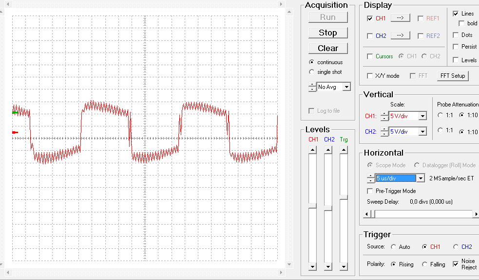
The first thing I did when I saw these lamps is connect an oscilloscope to the output of the supplies.
The transformer outputs a 50HZ 12VAC sine wave as expected. The other supply appears to be a switching supply. It outputs a 100KHz square wave with some high-frequency ringing. If you zoom out, it has a 50Hz envelope.
Solution
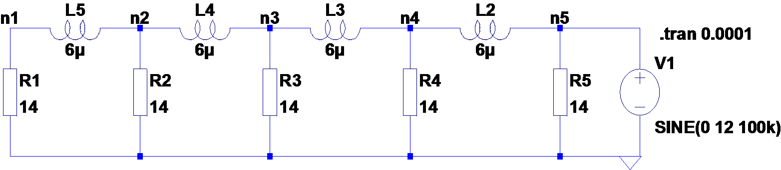
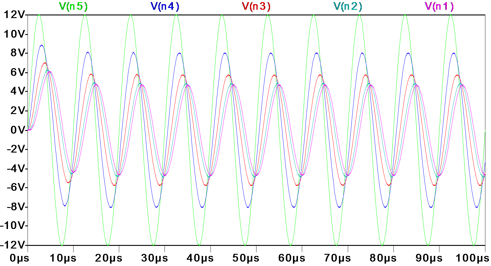
Since the only difference between the two setups is the frequency, the resistance of the wires is apparently negligible and the only thing that could have influence is the inductance of the wire.
Using an online calculator, I found that the inductance of 4m (10m back and forth divided by 5) copper wire is 3μH, and the resistance of the lamps follows from their rated voltage and wattage.
Last week I played some TIS-100, an assembly puzzle game where you are left to debug a fantasy computer with only the manual to guide you.
The TIS-100 is composed of many small nodes running a very limited assembly language with only one addressable register. Every node can however read and write data to its 4 neighbors.
After finishing the game, I remembered this talk by Chuck Moore on programming a grid of tiny Forth computers, not entirely unlike TIS-100, except more practical.
What if you could make an actual TIS-100? Not just an emulator, but an actual thing that sits on your desk. I set out to try.
I went to the electronics store and asked for a hand full of Attiny chips, which cost about one Euro each. They gave me some Attiny25, with 2Kb of flash, 128 bytes of ram, and 6 output pins.
I figured that with 4 neighbors and a clock line, I’d have exactly enough pins. But I’d have to do bi-directional communication over a single wire. So I decided on a pull-up design.
For now I’ll use the Raspberry Pi for input and output of the grid, but there is no reason this task can’t be delegated to another AVR chip and some buttons and 7-segment displays.
After a day of hacking, I can program 2 Attinies to double a number and pass it on. To run the more advanced puzzles, I’ll need a better way to upload code and more Attinies. I have yet to implement the stack memory node as well.
This is the code the two node currently run. (hardcoded)