For Mosaic, my open source schematic entry and simulation tool, I’m reevaluating the choice of GUI toolkit, and along with that the implementation language.
The original plan was to use Rust and GTK, but I’m slowly coming around to the idea that if its feasible performance wise to make a web app, that there is great value in that.
On the one hand IC designers are a conservative bunch and it’s great to have a good desktop app, but on the other hand EDA tools can be notoriously hard to set up and manage to the point where most commercial IC design happens via remote desktop.
Having a the option to a web app allows you to have a snappy interface without all the hassle, and as eFabless demonstrated allows people to do IC design without signing an NDA.
I kind of want the option to run as a desktop app or as a web app. So what are my options?
I think the most common one is to use Electron, which everyone likes to hate on, but in fact I’m typing up this blogpost in an Electron app and I can’t complain.
Another option would be Flutter, which has web and desktop targets.
And finally, some desktop GUI toolkits can be ran in a browser, which I’ll almost dismiss right away because they don’t behave like a proper web app.
This last point is worth reiterating on, because people keep suggesting canvas based systems such as Dear ImGui and Makepad.
These systems break basic expectations like being able to select text, tab through form fields, search, use onscreen keyboards, screen readers… the list is endless.
I will not write software that breaks basic expectations and is inaccessible to some people.
My plan is to make some very simple proof of concepts in various GUI toolkits to see how they stack up. I plan to look at
- Flutter (Not Electron!)
- TypeScript + React
- Elm
- Rust + Yew
- ClojureScript + Reagent
- Kotlin + React
I will consider the following criteria
- Ease of use
- Performance
- Not breaking basic shit
- Churn
By implementing the following tasks that I deem critical for my use as a schematic entry and simulation tool
- Schematic: Draw a bunch of SVGs and lines that can be panned and zoomed.
- Scripting: Interface with an IPython kernel for a minial notebook style interface.
- Plotting: Plot a simulation result with a lot of traces and time points that can be panned and zoomed.
Flutter
On the surface it seems like the dream combo.
Instead of a bloated Electron app you get a snappy desktop app that can also render to the web.
It’s not all roses though, it’s originally a mobile toolkit, and it kind of shows.
The desktop target it still in beta, missing advanced features such as “file picker” and “menu bars”, who needs ‘em right?
Flutter has a nice gallery where you can browse around some example apps.
I opened the email app and you can’t select the text in an email. Talk about “breaking basic shit”.
To continue on that point, I tried to access the app with a screen reader and on Android I just could not.
On Linux I managed to push the “enable accessibility” button, but all the actions in the email app are just “push button clickable” without further description.
They do bring up the on-screen keyboard in the compose window and increasing the magnification in Firefox did work, so there are some things they managed not to break.
On my desktop performance seemed good, but on my phone it is super janky. (jank seems to be the favorite word in the Flutter community) Curious to see how performance will hold up with my benchmarks.
Schematic
The code for drawing a hundred mosfets was quite okay. I added the flutter_svg library, added an a mosfet to the assets, and generated a hundred SVG widgets inside a Positioned inside a Stack inside a InteractiveViewer for the pan/zoom action.
I don’t particularly care about all the details for the moment, I just want to see how easy it is and how well it performs.
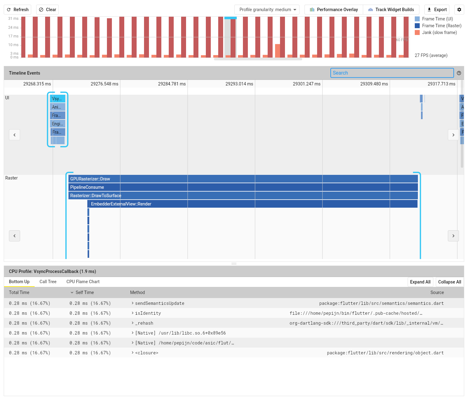
Pretty easy, but honestly it doesn’t perform that well. In release mode, with a 100 mosfets, it feels like it’s dragging along with like 15fps.
In profiling mode it instantly crashes. It actually seems faster in debugging mode though?!
According to the profiler it’s running at 30fps when I’m panning around.

Plotting
Of course step one is to locate a library. I checked out several.
The first was very fancy but doesn’t seem to offer panning and zooming.
The next gave a compile error because it’s not null safe and I’m not a savage.
The next is a commercial package which is a instant no-go for an open source project.
Then I posted on Stack Overflow and moved on.
I also had a look at the Discord server but it seems like the #help channel is just noobs like me asking questions with no one giving answers.
Notebook
There are two ways to go about embedding a IPython notebook.
One would be to use a webview, which is ruled out because it only supports iOS and Android.
The other is to implement it from scratch with Websockets, which is what I will do.
I figured I could use the code_editor package, but was once again foiled by null safety.
My understanding is that Flutter 2 does not allow nullable types by default, so packages that have not yet been updated can’t be used with it.
I’m sure there are ways to deal with this but for a quick test I just counted my losses and used a plain text field.
The async http and websocket code to connect to the IPython kernel was pleasant, and after a bit of fiddling, I managed to write this simple demo app that once you enter a token and connect, you can execute Python code.
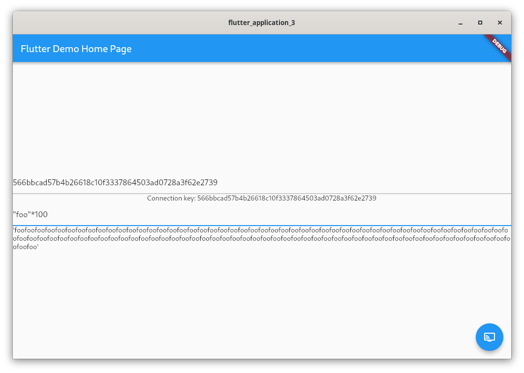
So while I got a good impression of async programming, I wasn’t able to get syntax highlighting to work, and am worried about how I will handle anything other than plaintext output.
One of the main powers of notebooks is being able to embed figures and even interactive widgets.
Without a Webview to reuse parts of the Jupyter frontend this becomes a difficult proposition.
Summary
Ease of use is quite okay. Installation was smooth, VS Code integration is amazing, hot code reload is sweet, programming in Dart is more or less fine, and working with async websockets was also fine.
Performance was quite disappointing, with the app unable to keep up the frame rate when panning around with 100 SVGs on the screen.
I was unable to test the performance of the plotting libraries because I was unable to find any that support interactive panning and zooming.
Breaking basic shit: yes. The fact that you can’t select text in an email app says it all.
Accessibility is also not great on the web, and in this beta completely absent when building for Linux.
In terms of churn, the ecosystem seems to be in the middle of a big migration to Flutter 2.
Flutter for desktop is also still in beta, so will likely see some breaking changes when it comes to using plugins for file pickers and menu bars.
On the other hand, with a significant community and the weight of Google behind it, Flutter is not likely to disappear anytime soon, and is on the whole a lot less fragmented than the JS ecosystem.
React + TypeScript
Basically I blinked and the entire ecosystem changed. Are Grunt and Gulp not a thing anymore? Is Yarn the new npm?
I would very much like to not rewrite my whole app every year.
But hey, React and TypeScript seem to be still around and going strong so that’s something.
I tried to figure out how to set this up and kinda just got lost in boilerplate.
I was about to just go back to Makefiles and script tags when someone pointed out Next.js which allows you to create an app with a simple yarn create next-app.
I’m sure it has a bunch of things I don’t need but at least it gets me a good setup with little hassle.
I had a look at nextron for making an Electron app with Next.js but it crashed while downloading the internet.
Aint nobody got time for that. I’ll start with a plain web app.
Next.js worked as advertised and had me editing a React app in TypeScript with hot reload in no time.
TypeScript is basically just JavaScript with type annotations, so it’s fine but not amazing.
Schematic
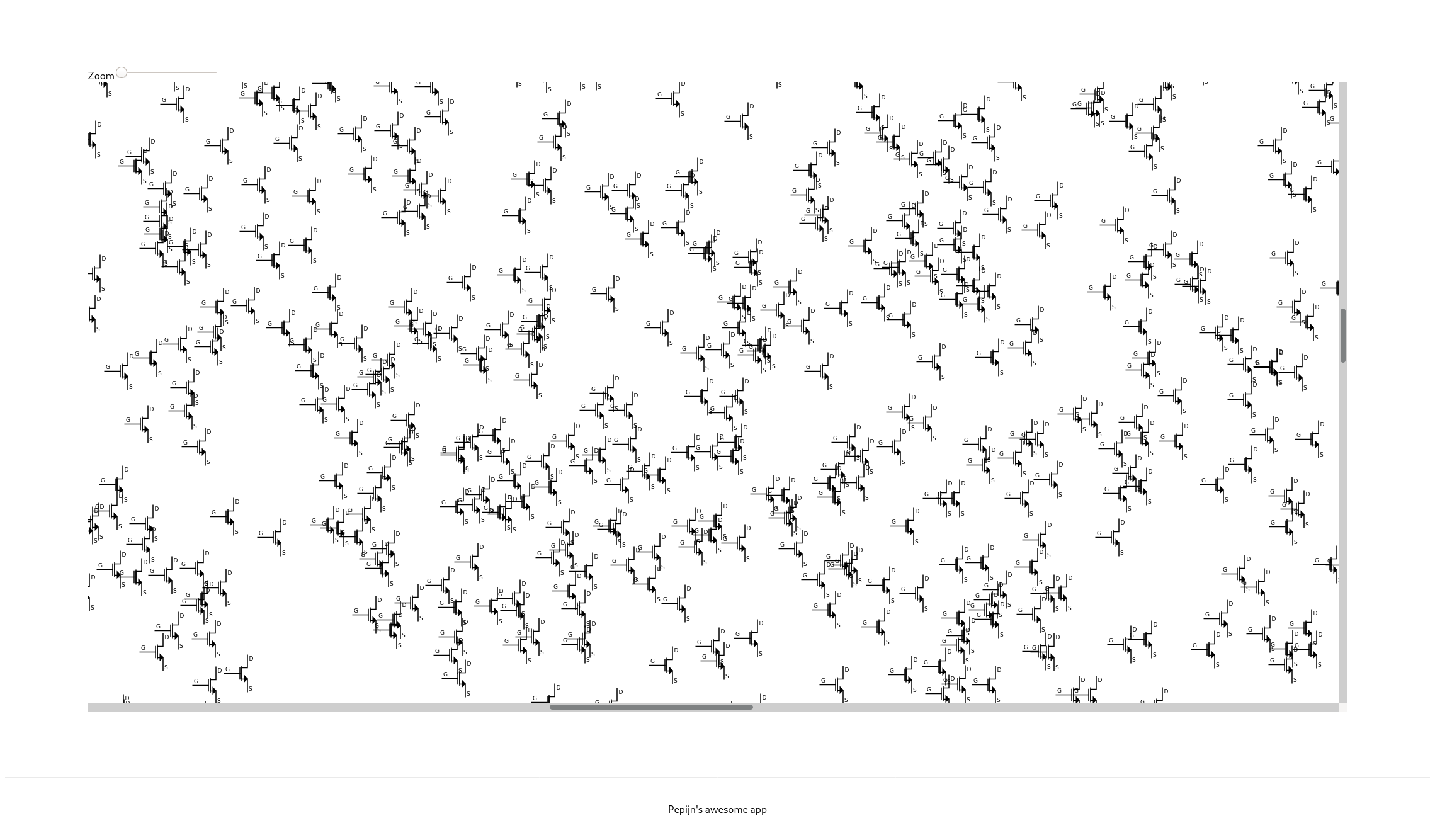
The start was pretty great. I made a for loop that inserts a bunch of <image> tags into an <svg> tag, and boom a hundred mosfets on the screen.
Then I tried to add scrolling but I forgot how CSS works.
I wrapped the SVG in a <div> with overflow: scroll but if I set the size to 100% it becomes as big as the <svg> and if I make it a fixed width, well, it’s a fixed width.
I should probably learn flexbox properly (I’m from the float days) but for now I just went with a fixed size.
Holy shit it’s fast. I cranked it up to 5000 mosfets and it’s still smooth as butter. Browsers are amazing.
Now for the zooming part, I figured I could listen for wheel events and if control is pressed, prevent the default behaviour.
But no such luck. After a bit of searching I gave up and just used a range input.
Hooking up the range input I ran into some JS this weirdness already, oh well…
The range input just sets transform: scale(value); which works well enough, but does not maintain scroll position.
Proper implementation left as an exercise for my future self.
Even zooming is quite amazingly fast. Only when zoomed all the way out does it struggle a tiny bit with redrawing 5000 mosfets, but it’s super smooth when zoomed in.
Plotting
It seems Plotly is a widely used plotting library for the JS world, so I went with that.
It even comes with a nice React wrapper, and can also be used in IPython notebooks.
For using with TypeScript it’s helpful to install the @types/react-plotly.js dev dependency to make the type checker happy.
But then I got bitten HARD by my decision to use Next.js for getting up and running quickly.
You see, Next.js tries to be all fancy with sever side rendering, and Plotly does NOT like this.
I’m not particularly interested in any of the features Next.js offers, I just don’t want to deal with all the boilerplate of setting it up manually.
In the end it turns out you have to use some dynamic import loophoole to avoid SSR and the resulting “document not found” errors from Plotly trying to access the DOM.
From there it’s smooth sailing to generate a bunch of data points and plot them.
Subplots were a small puzzle, but actually fine.
The interactive interface is very good, easy to pan and zoom around.
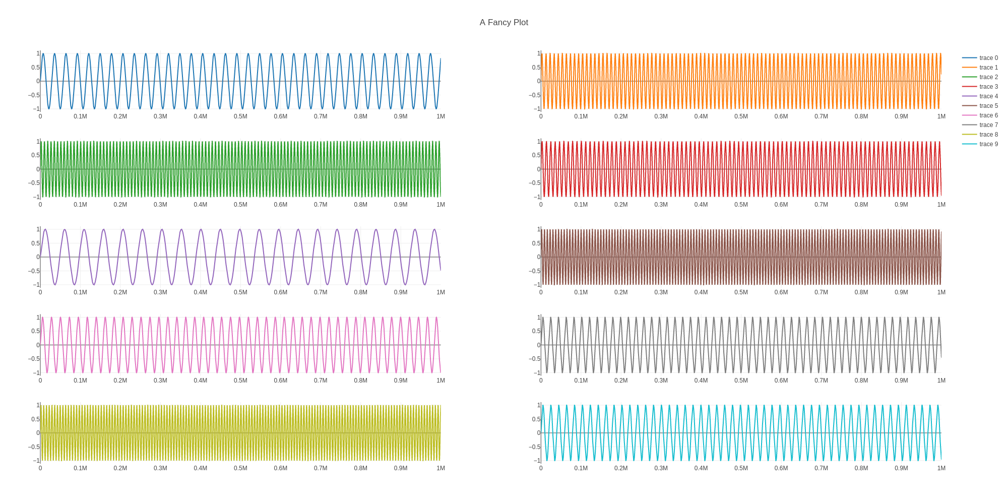
In terms of performance, I first made 10 traces of 100k points, which works fine.
But increasing it to 10 traces of 1M points sends performance completely off a cliff.
The interactive cursor updates with a few frames per second, panning and zooming hangs for a second, but once you start dragging it’s actually smooth until you release.
I did a bit of profiling, and it’s looping over the entire 10M points where it could probably be O(log(n)) by using some spatial index.
I reported an issue, where the maintainers suggested using scattergl instead, which improved panning and zooming.
Then I added hovermode: false to work around the last issue, and that gives very performant results all around.
In short, plotting works very well, but Plotly could use some improvements for very large datasets.
Notebook
I went ahead and asked on the Jupyter mailing list what would be the best way to integrate it.
I was pointed to an example that reuses Jupyter components to build a custom notebook.
It was also suggested I could embed my entire app as an extension into Jupyter Lab, which is not as crazy as it sounds as Jupyter Lab has grown into much more than just Python notebooks.
For now I’ll just try to follow the example though.
I tried with Yarn and that gave errors but then I tried with npm install; npm run build and it worked. Don’t ask me…
Npm told me there are 28 vulnerabilities (1 moderate, 27 high), so packages must be upgraded and the churn must continue.
It’s a bit of a different setup though, where the JS is compiled and then served with a Python script that is a subclass of Jupyter server.
That takes care of the kernels of course, but doesn’t give you the fancy hot reload.
I wonder if could somehow rig hot reloading into the bundled JS served by Python, but that’s for later.
For now I just want to see if I can interact with the notebook from the outside.
I found it quite hard to find good documentation on how to interface with the notebook, so I settled for just poking around a bit.
The commands.ts file provides some guidance for what sort of actions are available.
Call me barbaric, but the easiest way for me to play with the code was to assign the NotebookPanel and NotebookAction to the window object so I can access them from the browser console.
> nb.content.activeCellIndex = 0
0
> nb.content.activeCellIndex = 3
3
> nba.run(nb.content, nb.context.sessionContext)
Promise {<pending>}
> nb.content.activeCell.model.outputs.get(0).data["application/vnd.jupyter.stdout"]
"test\n"
I think that’s sufficient for now to know that it is possible to use Jupyter Lab as plain TypeScript modules and interact with the notebook cells in interesting ways.
The actual integration is going to be a bit of a puzzle though.
Summary
This whole setup honestly gave me quite a bit of puzzles, surprises, and headaches.
Next.js gave me an easy start with React, TypeScript, and hot module reload, but server side rendering bit me when I tried to use Plotly.
I will probably want to move to a pure React setup, but it won’t be enjoyable to set up.
HTML makes it very easy to draw arbitrary boxes and media, but on the flip side, making conventional widgets and interactions requires a lot more manual effort.
Like how Flutter just has a pan-zoom container, while I had a big struggle to make my SVGs zoom in and out.
Performance was honestly super impressive compared to Flutter.
Where Flutter compiled as a native Linux app struggled to pan and zoom 100 mosfets, Firefox just kept going with 5k of them.
I wasn’t able to compare plotting performance because Flutter just doesn’t seem to have a suitable plotting library, but the results with Plotly were quite impressive.
Granted, I had to switch to a canvas backend and disable hover behavior, but 10M points is no joke.
HTML allows you to select text! Amazing, I know, right? React wins the doesn’t-break-basic-shit badge.
Of course, unless you as the author break basic shit. Don’t do that.
Honestly the “churn” item is there because of the JS ecosystem.
Somehow they managed to build an ecosystem on top of a language that’s backwards compatible decades into the past, where as soon as you look away for a second your code bitrots away.
I hope that by sticking to the tried and true, I can avoid some of that. The big libraries seem to be here to stay.
Elm
For the remaining browser based solutions I will take a more lightweight approach.
Obviously all of them inherit the same performance characteristics when it comes to rendering HTML.
The plotting and notebook benchmarks are mainly about integrating libraries.
So for the browser based solutions I’ll be mainly looking at the strength of the package ecosystem or interop with the JS ecosystem.
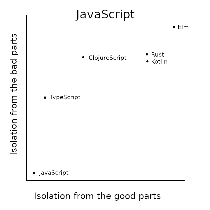
And frankly Elm just doesn’t cut it.
They take a pretty hardball stance on interop, requiring the package ecosystem to be pure Elm, and only allowing top-level “ports” to talk to JS code.
I had a look at plotting/charting libraries in Elm and none of them have been updated in the last 3 years.
Rust + Yew
The main concerns for me here are compile times and once again interop. I will try to plot a thing and see how it goes.
In Rust the dominant plotting library seems to be Plotters, but it’s fairly low-level and does not have built in pan/zoom.
Instead I’ll try using Plotly again.
Interop in Yew is similar to calling a C function.
There are example templates for webpack and parcel, so you can just npm install things.
I went with the parcel one, which told me once more there are a billion outdated dependencies and security vulnerabilities.
If you want to use the JS ecosystem you have to deal with the JS ecosystem. Obvious but true.
Running the example template is easy enough. It even reloads and recompiles automatically, though it’s not hot module reload, just a page refresh.
On this small example, compile times are short, not sure it’ll stay that way.
A tendency of JSX-like Rust macros is that they require an ever-increasing recursion limit and result in slow compile times.
After several hours of trying to integrate Plotly by fiddling with annotations, I can confidently say: screw that.
ClojureScript
I used to do a lot of Clojure some years ago but never really got into ClojureScript.
Clojure has always had good interop, and a functional programming approach without static typing.
Not having static types reduces friction, but makes debugging harder.
In particular, Clojure has mostly useful default behaviour for handing nil rather than forcing you to handle Maybe results, until you get a null pointer exception and you’re in for a mystery hunt.
The tooling seems not as mature as some other languages.
There seem to be two major Clojure/ClojureScript VS Code extensions, neither of which supports debugging ClojureScript.
The on I tried complained about me using VIM mode…
I’m once more just going to try to integrate Plotly and see how it goes.
The official website lists several abandoned projects which is not a good look.
I asked about it on Slack and and they maintain that once software is done it requires no updates ever. It’s perfect, don’t touch.
Which is honestly kinda refreshing compared to JS land where you have to burn everything to the ground perpetually.
But you also have to be realistic about it, if a project has a bunch of open issues and PRs it’s maybe not as perfect as you say.
At first I went with Leiningen and Figwheel based on my experience from a few years back,
but along the way learned from friendly community members that these days tools-deps is the standard way to bundle apps and shadow-cljs is the new hotness when it comes to ClojureScript tooling.
Both Figwheel and shadow-cljs offer a nicely integrated development environment with state preserving hot code reload and a REPL into the running app but shadow-cljs has better integration with npm.
I created a new project with npx create-cljs-project cljsplotly and from there added Reagent (a react wrapper) and copied some example code.
Compiling and running the project is as simple as npx shadow-cljs watch frontend, and its not even like there is a ton of boilerplate, just the simple config files for npm and shadow-cljs.
Then I added react-plotly.js as a regular npm dependency.
After that I was able to import the library with ["react-plotly.js$default" :as PlotComponent], and define it as a reagent component with (def plot (r/adapt-react-class PlotComponent)), which can then simply be used like so [plot {:data (clj->js [{:x [1 2 3 4], :y [1 2 3 4], :type "scatter"}])}].

Kotlin
I wasn’t even planning on covering this option, but it popped up along the way and I figured I might as well check it out.
I mainly know Kotlin as a very pragmatic “better java”, and have used it once in this capacity.
Apparently it now also supports native and JS targets, with what looks to be favorable options.
Right away the first struggle is the tooling. The setup page only refers to IntelliJ with some mentions of the actual Gradle stuff.
I’m sure you can use plain Gradle to do it, but for getting started, not ideal.
It seems that the VS Code plugins are comparatively basic.
So I guess I’m installing IntelliJ and figure out another workflow later if needed.
Setting up a project was easy.
From there things got a bit confusing.
There is a debugger, but it debugs the JVM server process.
You can use the browser debugger, but sourcemaps aren’t working for me. (this turns out to be because you have to us the LEGACY compiler for that)
It has hot code reload, but not state preserving, it just reloads the page.
Installing an npm dependency is pretty easy, but then you run into the exact same problems as with Rust where you have to add some externs with magic annotations to declare the JS interface.
The tutorial for adding a React component has the following helpful information on the matter
Because JavaScript imports/exports isn’t the simplest topic, it can sometimes be tricky to find the correct combination between annotations to get the Kotlin compiler on the same page as us.
Again, I tried for a good while and asked on Slack.
A day later a suggestion came in and after a bith more back and forth I managed to get it to work.
I still do not understand why or how, and how I would go about future JS interactions.
I also had a bunch of trouble just making a JS object to pass to the component.
In short the interop story isn’t very obvious.

Conclusion
I had high hopes for Flutter, but it was pretty disappointing across the board. Poor performance, poor accessibility, poor libraries.
Browser performance when drawing 5k SVGs was amazing, and so was Plotly performance when drawing 10M points, once I used the right settings.
So the web is definitely the way forward.
React is good, TypeScript is a minor improvement over JavaScript, but honestly the worst part is the tooling and quirky browser APIs.
If I have to, I’m sure I can make it work. Not sure it’ll be the most enjoyable thing in the world though.
I dismissed Elm for lack of libraries. Rust and Kotlin seemed interesting, but their hot code reload does not maintain state, there is no REPL, and I had a lot of trouble making JS interop work.
I’m sure they work well for some people, but I just could not make them work well for me.
ClojureScript was a very pleasant homecoming. I had kind of stopped using Clojure because a lot of what I do these days is either scientific Python/Julia scripts or embedded C/C++/Rust, but it’s a nice language.
The community was very helpful and welcoming, with some old friends still around.
It has by far the nicest toolchain and workflow of all the compile-to-js systems I tried, and the only one that can come close to TypeScript in JS interop.
So in the end I think the competition is between ClojureScript and TypeScript.
I had a lot more fun with ClojureScript, but of course it’s a less widely used language.
TypeScript, for better or worse, is more mainstream and closer to JavaScript.
